

Helio-STELLA
The Helio-STELLA is a specialized member of NASA’s Science and Technology Education for Land/Life Assessment instrument family, designed specifically for heliophysics and solar observation.
This innovative handheld device features a spectrometer that measures light across the 415-680nm spectrum, complemented by a UV sensor detecting radiation at 320nm. The instrument’s distinctive design includes a white ping pong ball diffuser that optimizes light collection from various angles. Assembly requires no soldering—simply connect the components.
The Helio-STELLA displays data on a compact screen, with an intuitive pushbutton interface to cycle through different measurement screens and toggle the reference lamp. The Helio-STELLA makes solar spectroscopy accessible to students, educators, and citizen scientists interested in exploring our sun’s electromagnetic properties.
To build your own Helio-STELLA download the Helio-STELLA files and follow the build steps.
Helio-STELLA Highlights

Students Build AI-Powered Drone for Earth Observation | NASA SEES Internship Journey
Four high school students leveraged STELLA's accessible design, supportive community, …

NASA SEES Students Showcase EarthLens-STELLA Integration at AGU 2025
NASA STEM Enhancement in Earth Sciences (SEES) interns Nandini Khaneja, …
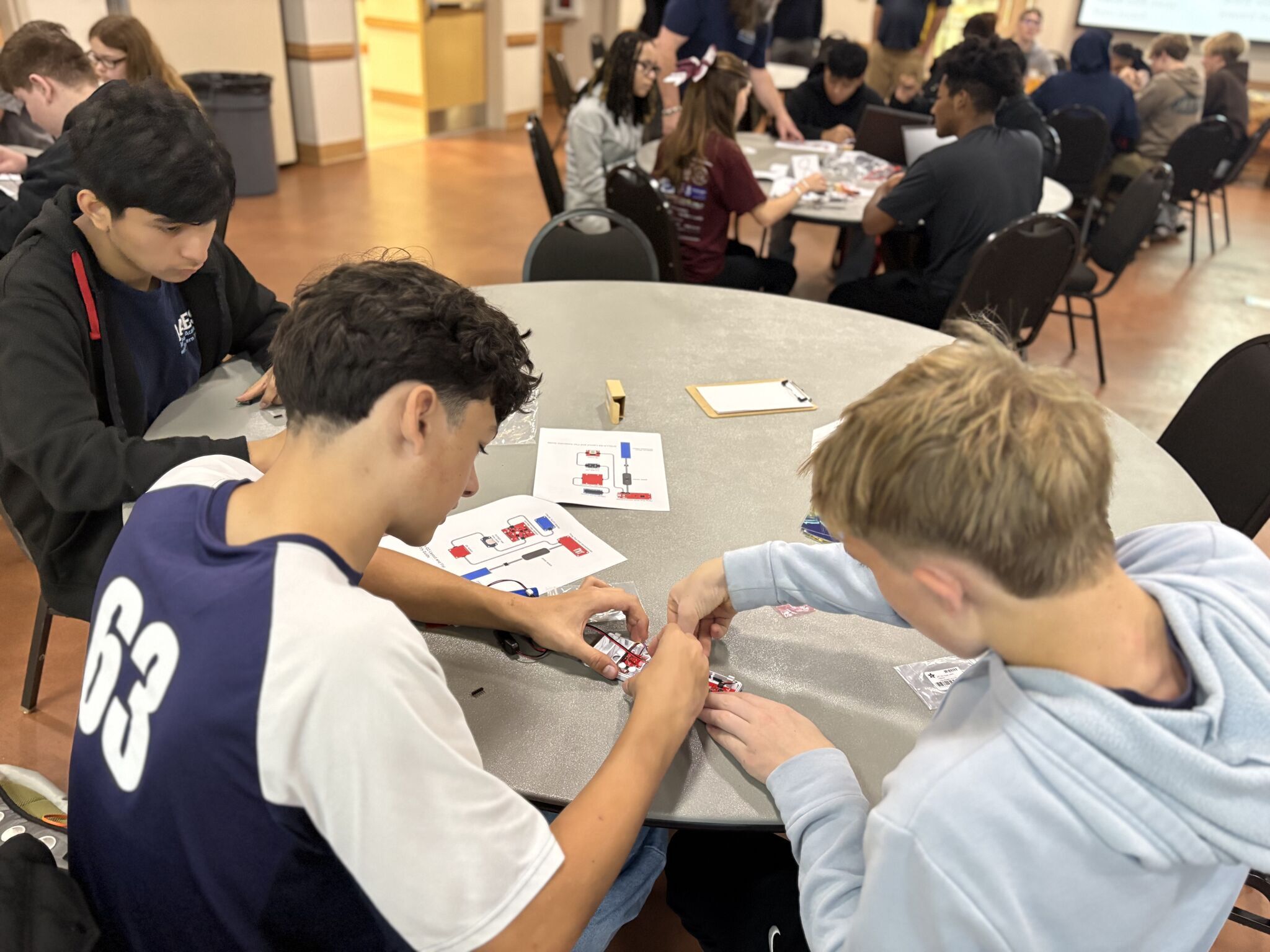
AAES Brings NASA’s STELLA Remote Sensing to Virginia’s Eastern Shore
The Aerospace Academy of the Eastern Shore (AAES)—a STEM-focused lab …
Helio-STELLA Build Steps
| Parts for Helio-STELLA | |||||
|---|---|---|---|---|---|
| Line | item | qty per unit | cost each | manufacturer | manufacturer # |
| 1 | glue stick (3pk) | 0 | 3 | ||
| 2 | colored gel set | 0 | 13 | ||
| 3 | ping pong balls (50) | 0 | 10 | ||
| 4 | colored ping pong balls (28) | 0 | 7 | ||
| 5 | double stick mounting tape 100 pcs | 0 | 6 | ||
| 6 | spectrometer | 1 | 16 | Adafruit | 4698 |
| 7 | UV sensor | 1 | 5 | Adafruit | 4831 |
| 8 | real time clock | 1 | 5 | Adafruit | 5189 |
| 9 | clock battery | 1 | 1 | Digikey | 490-18640-ND |
| 10 | display | 1 | 13 | Adafruit | 4440 |
| 11 | microcontroller | 1 | 20 | Digikey | DEV-17745 |
| 12 | sd card | 1 | 4 | Adafruit | 5250 |
| 13 | i2c button | 1 | 5 | Digikey | BOB-15932 |
| 14 | power switch | 1 | 1 | Adafruit | 3064 |
| 15 | battery | 1 | 10 | Adafruit | 1781 |
| 16 | usb cable | 1 | 5 | Digikey | DH-20UE0063-NH |
| 17 | sd card reader | 1 | 7 | Adafruit | 5212 |
| 18 | qwiic cables | 6 | 1 | Adafruit | 4210 |
Step 1 – Use a small sharp knife to cut the LED trace on the back of the AS7341 spectrometer
module to disable the green LED on the front. (Fig.
1.)
Step 2 – Cut a piece of corrugated cardboard to 8.5
x 11” or a little larger.
Step 3 – Apply glue stick to the back of the layout sheet, then stick the layout sheet to the cardboard.
Step 4 – Cut the two holes marked on the layout sheet, through the sheet and the cardboard.
Step 5 – Apply pieces of double sided foam mounting tape to the back (Kat side) of the modules. Trim the excess.
Step 6 – Stick the modules to their corresponding locations on the layout sheet.
Step 7 – Connect the modules using the cables provided. The cables are built so they only connect in one orientation. Don’t force the connections. (Fig.
2.)
Step 8 – Slide the micro SD card into the slot on the back of the microcontroller.
Step 9 – Click the power button to turn the Helio-STELLA instrument on. If it’s already on, it’s helpful to turn it off, wait a second, and turn it on again.
Step 10 – The instrument should start up, showing the display screens in the boot cycle. See the operating instructions for more
information on the screens.
Step 11 – Cut the ping pong ball in half, leaving some tabs for taping it down. (Fig 3.)
Step 12 – Position the ping pong ball over the AS7341 spectral sensor, and tape it down at the edges or on the tabs. Don’t run tape over the surface of the ping pong ball, to keep the tape from affecting the light reaching the sensor.
Step 13 – Place the instrumentin direct sunlight. Leave it running throughout the eclipse!

Step 1: Load CircuitPython onto the Microcontroller.
1. Locate the CircuitPython file in the Helio-STELLA/CircuitPython_uf2, named “adafruit-circuitpythonadafruit_feather_rp2040-en_US-8.0.5.uf2”. The file is specific to this particular microcontroller. The original source of the file is:
https://circuitpython.org/board/sparkfun_thing_plus_rp2040/
2. Connect the STELLA to your computer with a USB-C cable.
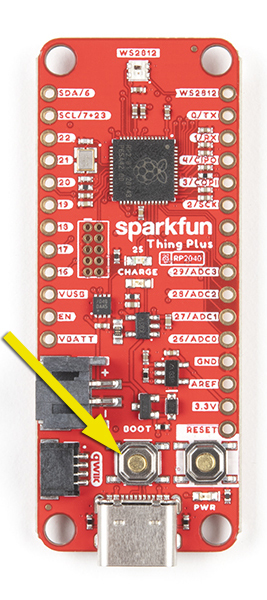
3. The STELLA should show up in your computer’s drive listing as RP1-RP2. If not disconnect from USB-C then
hold Boot button (yellow arrow) and plug back in.
4. Drag and drop the UF2 file onto the RP1-RP2 drive. The drive will disappear (and the 2le system will complain
about not ejecting the drive properly, that’s normal). The drive will reappear as CIRCUITPY. CircuitPython is now active on the STELLA.
Step 1: Load CircuitPython onto the Microcontroller.
1. Locate the CircuitPython file in the Helio-STELLA/CircuitPython_uf2, named “adafruit-circuitpythonadafruit_feather_rp2040-en_US-8.0.5.uf2”. The file is specific to this particular microcontroller. The original source of the file is:
https://circuitpython.org/board/sparkfun_thing_plus_rp2040/
2. Connect the STELLA to your computer with a USB-C cable.
3. The STELLA should show up in your computer’s drive listing as RP1-RP2. If not disconnect from USB-C then
hold Boot button (yellow arrow) and plug back in.
4. Drag and drop the UF2 file onto the RP1-RP2 drive. The drive will disappear (and the 2le system will complain
about not ejecting the drive properly, that’s normal). The drive will reappear as CIRCUITPY. CircuitPython is now active on the STELLA.
Step 2: Setting the Time
1. Open Mu Editor.
2. Turn on the STELLA, and plug it in to your computer.
3. Click on the Serial button at the top of the Mu window.
4. In the Serial Dialogue panel that opens at the bottom of the Mu window, you should see a line of text that loads every second:
“Memory B: Used xxxxxx /Free xxxxxx recording…”
That tells you that Mu is communicating properly with the STELLA.
5. Open the Finder (on a Mac) (File Explorer in Windows). Find the CIRCUITPY drive in the 2le list. Click on it to load it into the
window. You should see three items: boot_out.txt, code.py, and a folder called lib.
6. In another Finder/Explorer window your computer, in the code 2les that you downloaded for programming the STELLA, open the folder called test_codes. In there you should 2nd a folder called real_time_clock, and in that folder you should 2nd a file named code.py
7. Copy that code.py 2le, and paste it onto the CIRCUITPY drive. (Drag and drop should also work) The system will ask you if you want to replace the existing code.py file, and you should choose to Replace.
8. Now go back to the Mu window. In the Serial panel it should be printing out the date and time, once a second. That shows that you have the real time clock test code running on the STELLA. The STELLA screen itself should be either blank, or showing the same printout as you are seeing in the Serial dialogue.
9. Now click on the Load button at the top of the Mu editor. You should see the contents of the CIRCUITPY drive. If you see some other contents, change the choices so that you are looking at the CIRCUITPY drive. (If you save a file somewhere else on the
computer, it will not run on the STELLA, but Mu doesn’t warn you about that, or offer a Save As button to correct that)
10. In the Load window, select the code.py file on the CIRCUITPY drive, and the real time clock test code should load in the Mu window.
11. There is a line of code that reads “if False”. Change that line to “if True”. It’s important to get the capitalization correct (lower
case if, upper case T in True).
12. Open a web browser window, and navigate to time.is/UTC to get a readout of the current global universal time.
13. A few lines below the “if True” line is a line “t = time.struct_time((…))” That line is a bit out of date by now. Change the line as follows: I’m setting my STELLA as I am writing this, so the line now should read:
t = time.struct_time(( 2022, 09, 30, 19, 38, 00, 5, -1, -1))
I’ve set the seconds to 00. 5 designates the day as Friday, and the -1, -1 tells the clock not to set the day of the year or ‘is daylight
savings’ field.
14. Wait for the web UTC clock to get within two seconds of the time you’ve put in the time.struct line, and then click the Save button at the top of the Mu editor. That sets the real time clock module on the STELLA. The printout in the Serial panel should show
the correct time now.
15. To make sure we don’t save again and reset the time incorrectly, change the “if True” line to “if False”. Then save the code again. The Serial printout should continue to show the correct time.
16. Now go back to the Finder/ Explorer, and locate the STELLA-Q-code-and-libraries folder. . Copy the code.py from there to the CIRCUITPY drive, choose to Replace the existing file, and the STELLA should run the full instrumentation, now with the correct time.
Step 3: Programming Helio-STELLA
Now that you have CircuitPython installed on the microcontroller, you are ready to program your STELLA-AQ.
1. Download the .ZIP 2le that contains the latest software.
2. In the folder labelled “code and libraries”, copy the folder named “lib”, and paste it onto the CIRCUITPY drive. (You can also drag
and drop it to the CIRCUITPY drive.) You may get a message that the folder already exists; choose to replace the existing folder.
3. From the same “code and libraries” folder, select the 2le named “code.py” and copy/paste or drag/drop it onto the CIRCUITPY drive. The code should start up (it takes 12 seconds to boot) and you will have a working Helio-STELLA. We’ve written the code so that it is tolerant of missing devices, so even if you haven’t got all the parts it should still work.
4. In the “test codes” folder, there is a subfolder called “real time clock”. Inside that folder is a file named “code.py” Copy and paste that file to the CIRCUITPY drive to set the real time clock. Follow the detailed instructions here to set the clock.
5. Once the clock is set, repeat Step 3 to install the STELLA instrument software.