

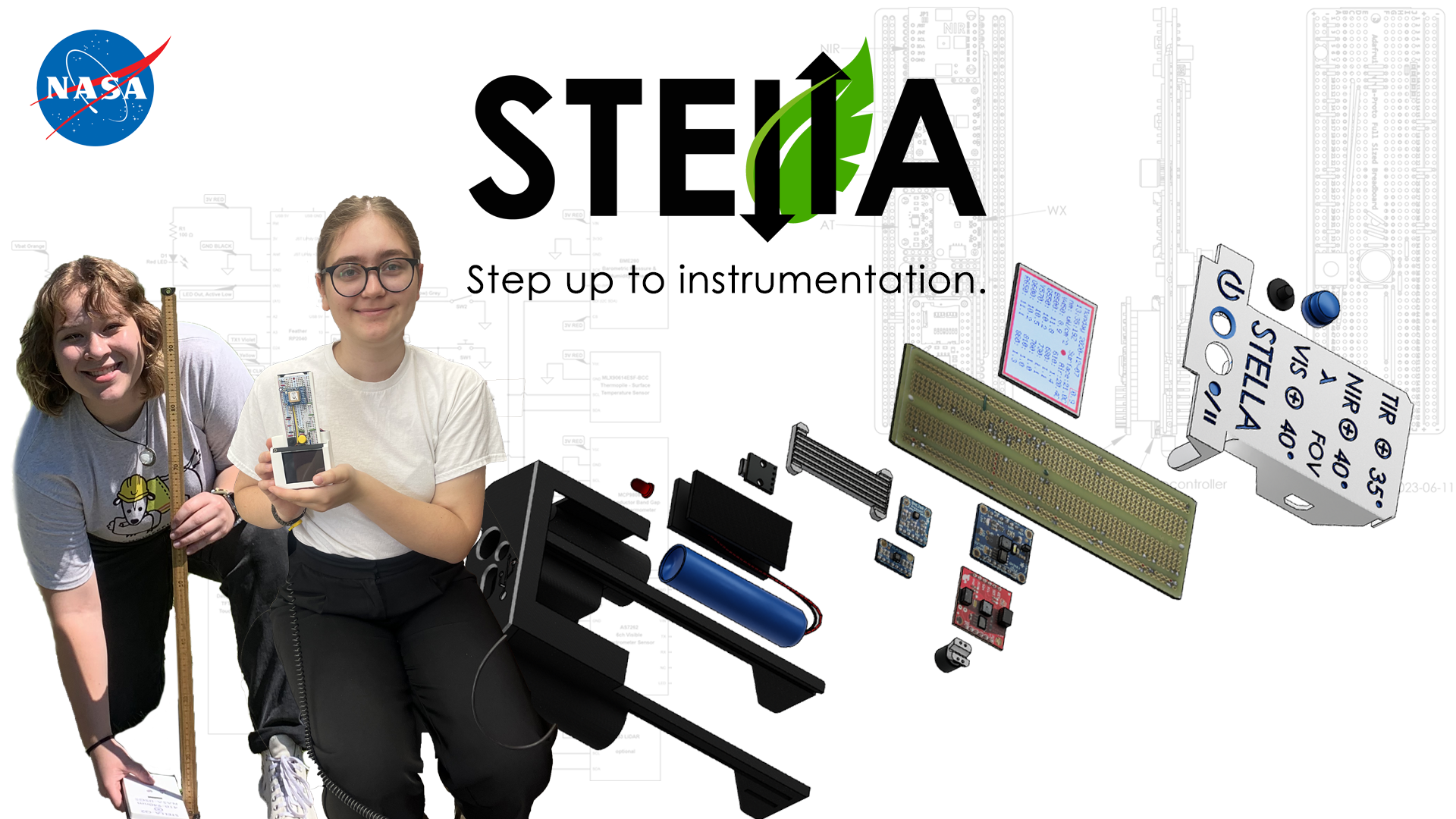
STELLA-1.1
The STELLA-1.1 is a low-cost, handheld scientific instrument that is part of the STELLA (Science and Technology Education for Land/Light Assessment) suite. It features a spectrometer with 12 channels combining a 6-channel visible sensor (AS7262) and a 6-channel near-infrared sensor (AS7262). The device records data digitally to a micro SD card with time stamps and batch numbers, and includes a color display screen with touch-response controls.
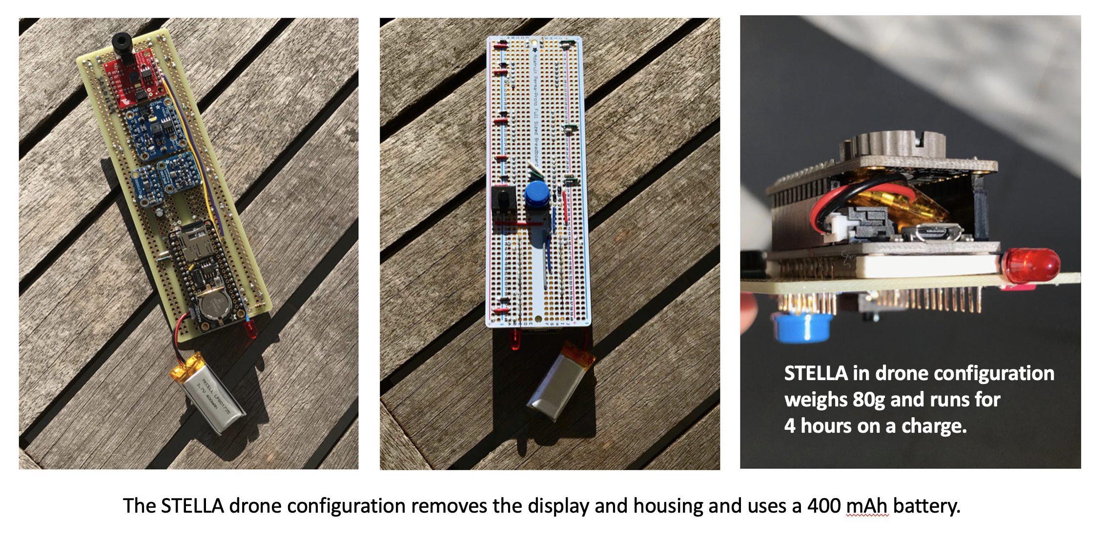
The STELLA-1.1 requires soldering and 3D printing for assembly, with its housing using snap joints that require no glue, tape, or screws. Weighing less than 100 grams, it can be easily adapted for drone use.
While this version is currently in use, it is expected to be replaced by the more advanced STELLA-1.2, which offers greater sensor customization options and additional capabilities such as GPS location data and range sensing LiDAR measurements.
To build your own STELLA-1.1 download the STELLA-1.1 files and follow the build steps.
STELLA-1.1 Highlights

Petya in the Field
Watch Dr. Petya Campbell, a NASA Goddard research scientist with over 20 years of field …
Student Voices: Real Engineering Success with STELLA Instruments
When Inna and Alexa first encountered NASA's STELLA instruments, neither expected the transformative journey ahead—from …
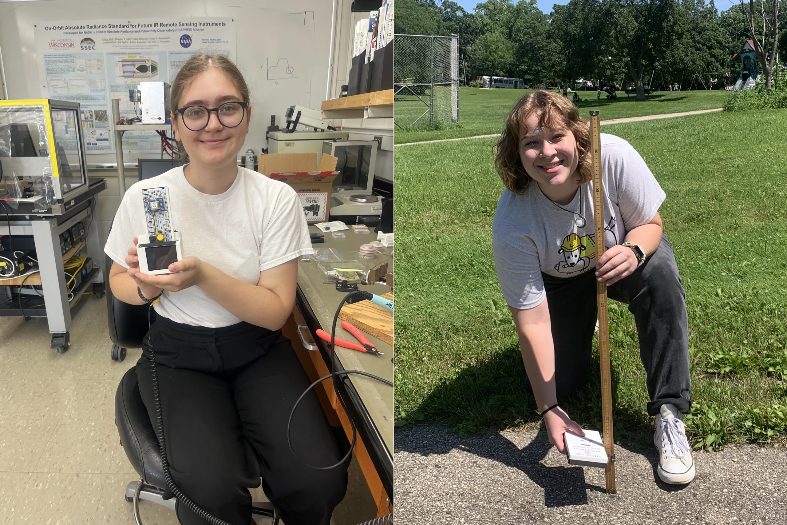
Inna Shapovalenko and Alexa Matson: Open-Source Engineering for the Future STEM Workforce
Inna Shapovalenko and Alexa Matson's collaborative journey with the STELLA project showcases how open-source engineering …
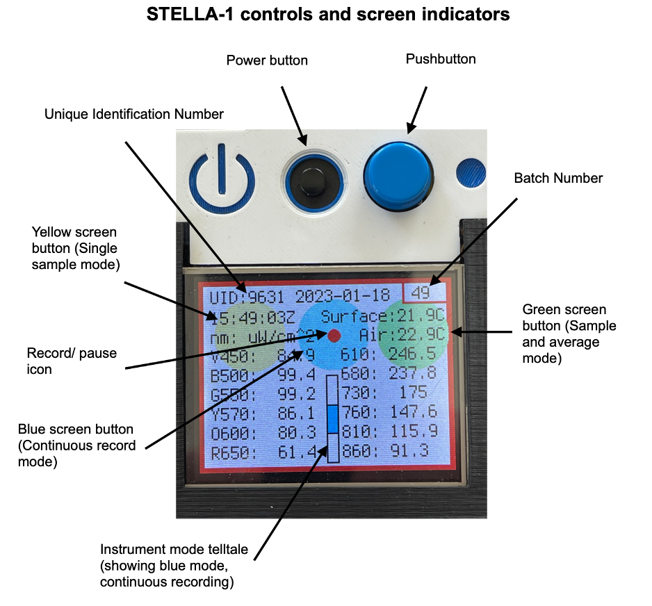
Controls and Screens
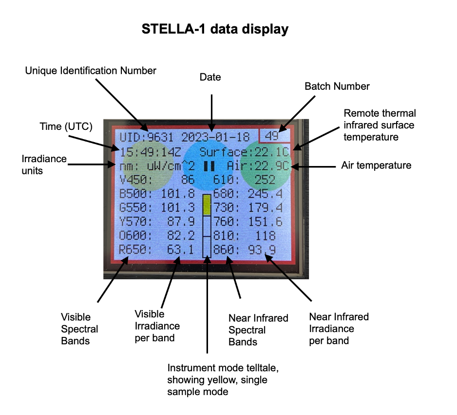
Data Display
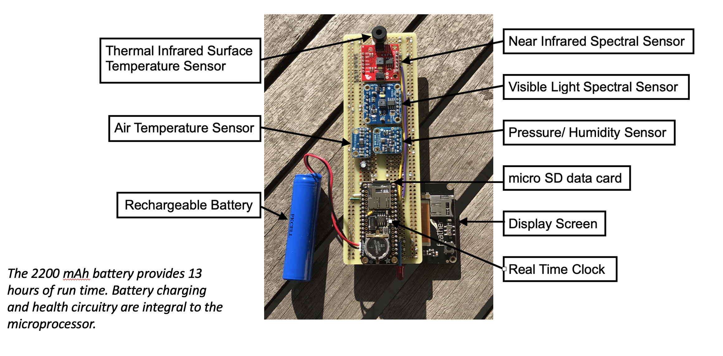
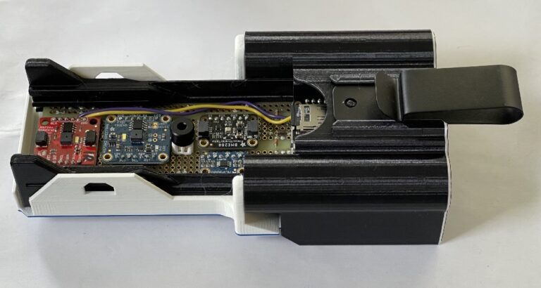
What's Inside
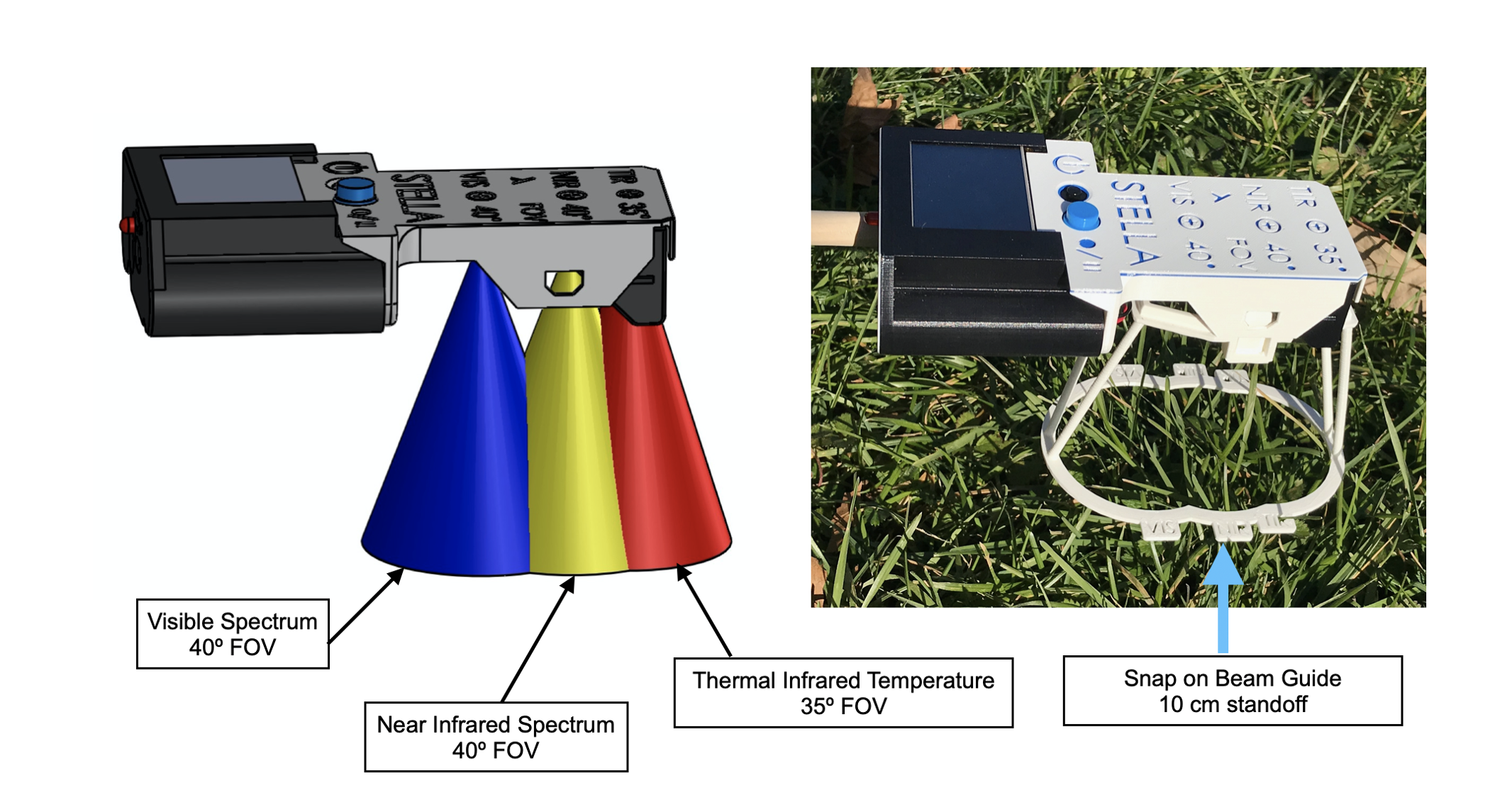
Where STELLA "Looks" (Field of View)
STELLA Can Ride on a Drone
STELLA-1.1 Build Steps
3D Parts Required
Lower Housing
Top Housing
Screen Mount
Processor Spacer
Thermal IR Spacer
Tools Required
-
Wire cutter
-
Wire stripper -- 26-22 AWG
-
Needle nose pliers
-
Soldering iron, with a soldering iron stand
-
Lead-free solder, SAC305 alloy: Sn (tin) 97%, Ag (silver) 3%, Cu (copper) 0.5%
-
Desoldering braid
-
Safety glasses
-
Soldering fume exhauster
-
Full size breadboard, for use as an assembly fixture
-
Computer: A computer running either Apple Macintosh or Microsoft Windows operating systems
-
3D printer, fused filament type, 20 cm cube printing volume
-
Printer filament: black, white, blue
-
Ruler
-
Thin film double stick tape, for mounting the power buttonOptional
-
Solder sucker: suction desoldering toolOptional
Note: The 3D thermal sensor spacer and 3D Feather spacer should be printed before assembly.
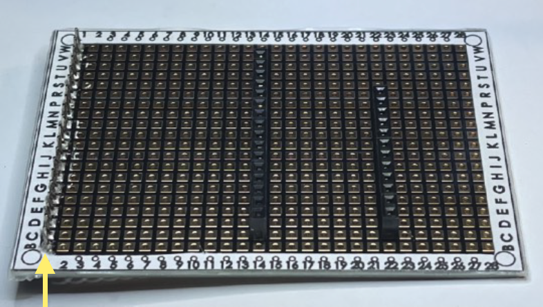
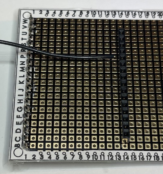
Build Steps - Part 1 Wiring
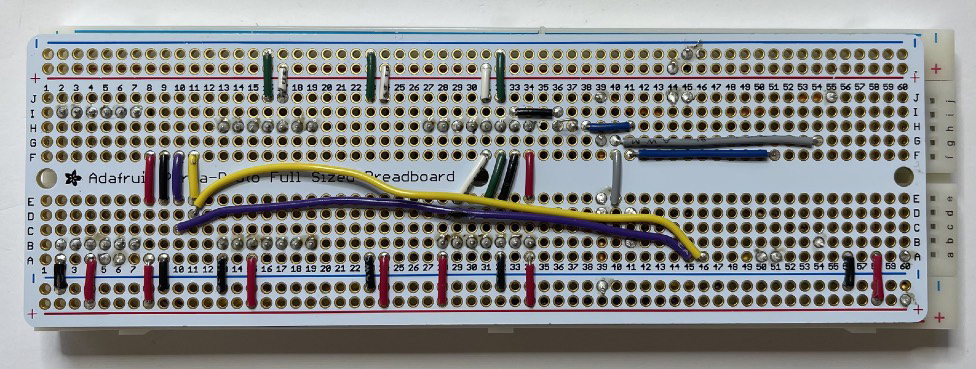
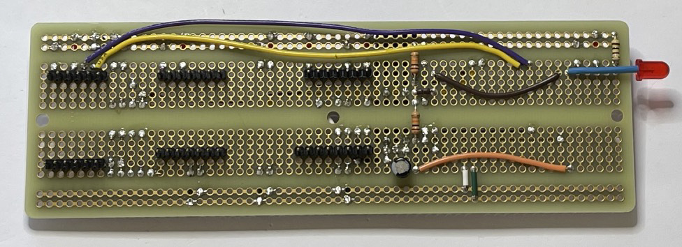
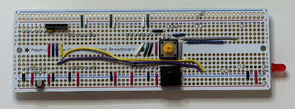
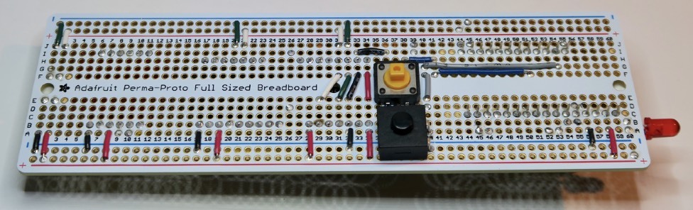
Following the STELLA-1.1 Wiring List, install and solder the resistors and then the wires. Lines 1 to 45 in the list. Leave some slack, as shown in the photos, on the yellow and violet wires, so that you can move them a bit when installing other components.
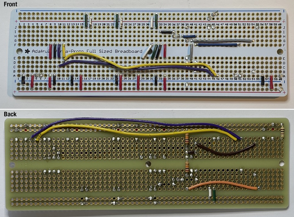
Double check your wiring against the wiring list to make sure that you have installed the wires correctly. It’s a lot easier to fix problems now, than to move wires around after other components are in place.
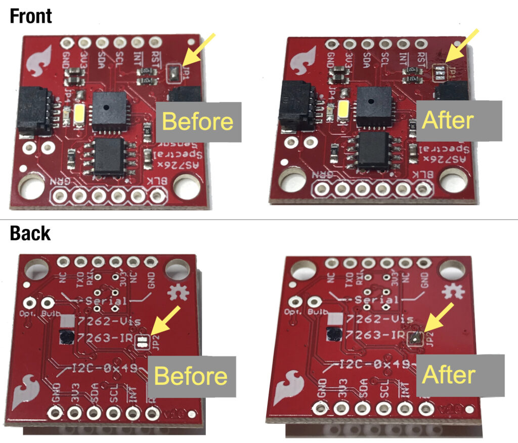
Build Steps - Part 2 Modify Near Infrared Sensor
Build Steps - Part 3 Install Headers
Lines 47 to 50. Break pin header segments to the required lengths, then fixture the segments in a breadboard.
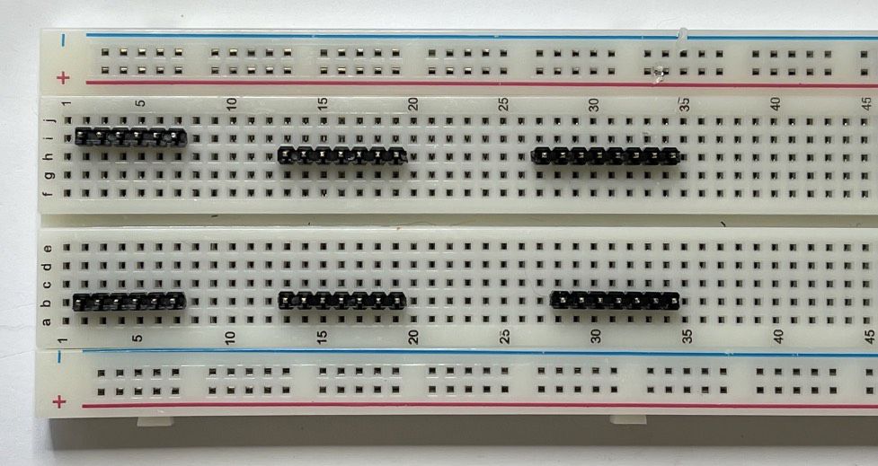
Place the STELLA main board on the fixture assembly, checking that the pins show in the correct locations on the board. Solder the pins in place, then carefully pry the board with the pins off of the breadboard fixture.
Build Steps - Part 4 Short Socket Header
Build Steps - Part 5 Discrete Components
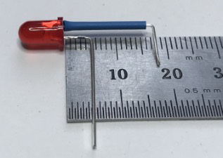
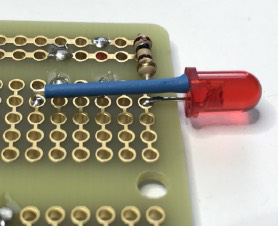
Lines 52 to 57. Install the remaining discrete components. Bend the LED leads, and install a piece of tubing, as in the photo. Note that the longer, positive lead is the one that we bend at 5mm, and the negative lead, near the LED case flat, we bend at 18mm.
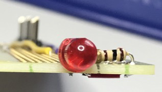
Note also that the electrolytic capacitors (10 uF) have a white stripe to indicate the negative lead, and that the positive lead is the longer of the two. Install them in the correct polarity according to the wiring list.
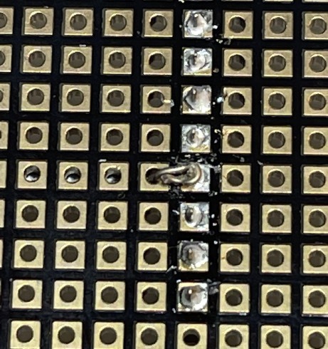
Build Steps - Part 6 Modify the Datalogger
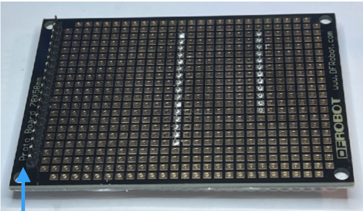
Line 58. Modify the datalogger by cutting the circuit trace labelled SDCS, and adding a wire to connect the SDCS to a new location (D11).
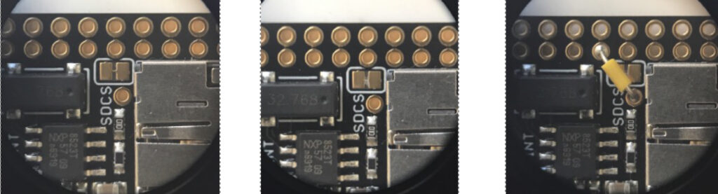
Datalogger after trace cut.
Datalogger after trace cut.
Datalogger with SDCS wire in place.
Using the breadboard as a fixture, install the header pins on the outer sets of holes on the datalogger.
Build Steps - Part 7 Microprocessor
Line 59. Using the datalogger as a fixture, place the stacking headers and install and solder the Feather RP2040 microprocessor.
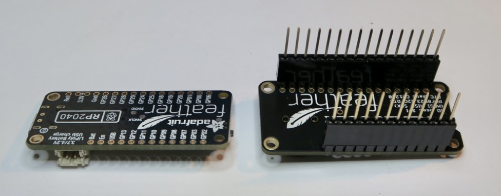
Then place the 3D printed part “feather spacer” on the back of the microprocessor.
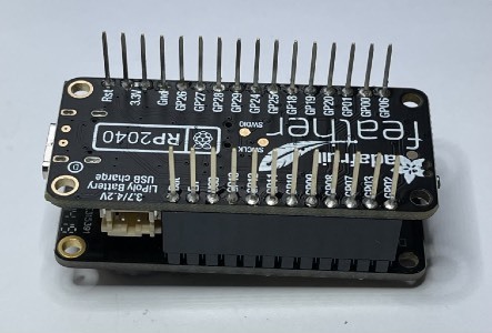
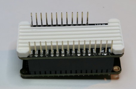
Lines 60 and 61. Mount the microprocessor to the main board assembly and solder the pins in place. Solder these joints carefully, to avoid getting solder on the tips of the pins, which we will use later to connect to the display.
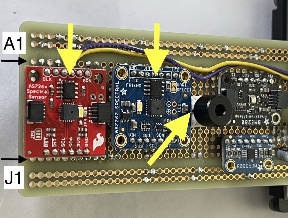
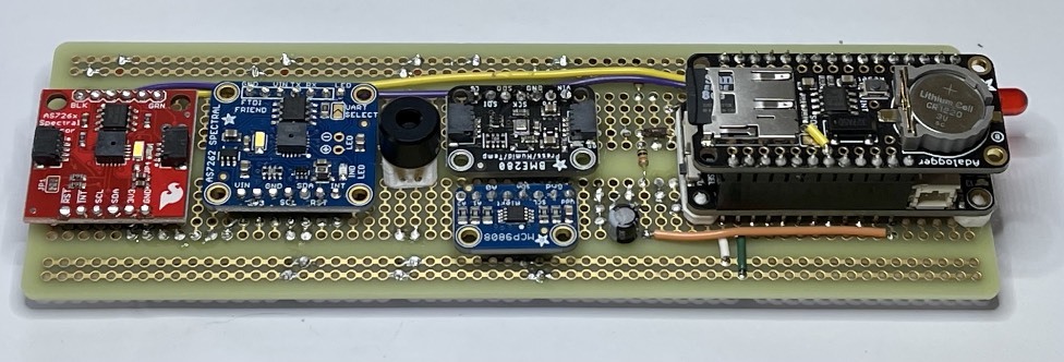
Build Steps - Part 8 Mount Sensors
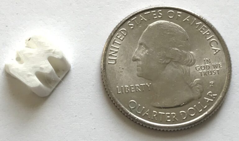
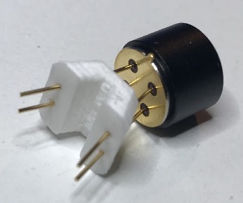
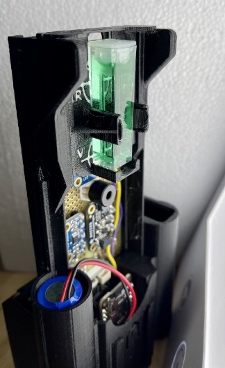
Lines 62 to 66. Mount the sensors. Install the Thermal Infrared (TIR) sensor on the 3D printed part “TIR sensor holder 4.5mm” before installing it on the main board.
Note the position of the orientation tab, towards the VIS Spectral Sensor, as indicated by the angled yellow arrow.
Also note the location of the communications chips on the spectral sensors. The sensors should be installed so that these chips are closest to the A row, as indicated by the yellow arrows.
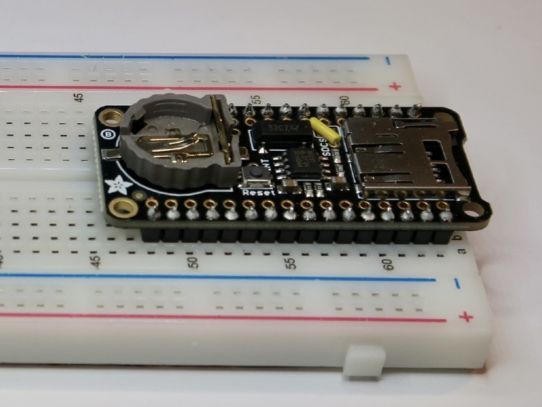
Install the datalogger by stacking it on the microprocessor. Insert the clock battery and micro SD card.
Build Steps - Part 9 Display Board
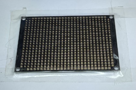
Prepare the display mount board: On an ordinary office paper printer, print the file “protoboard DFRobot FIT0203 print” at full scale. Apply clear double stick tape to the protoboard, then apply the printed column and row dataframe, and trim the excess and center out as shown.
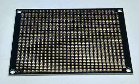
Orient the board so that the VCC label Apply clear double stick tape to the shows in the upper left, and the GND label outer frame of the board. is in the lower left.
Orient the board so that the VCC label Apply clear double stick tape to the shows in the upper left, and the GND label outer frame of the board. is in the lower left.
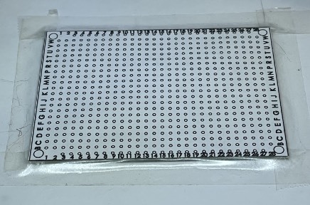
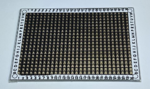
Carefully align the print to the edges of the board.
Trim the excess tape from the outer edge and remove the central part of the print.
Build Steps - Part 10 Display Board Headers
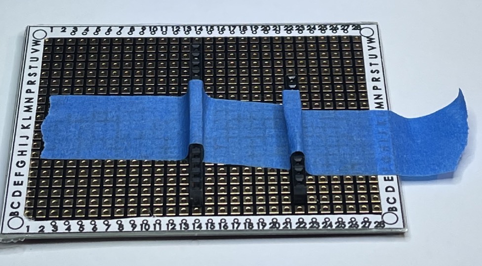
Line 70. Install a 20 position pin header from the back of the board (blue arrow), and solder it on the front (yellow arrow)
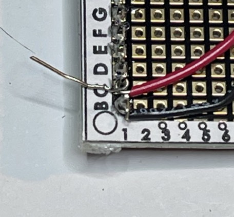
Lines 71 to 80. Connect wires to header socket positions. Since the board does not have traces that connect any hole to any other hole, we must make the connections ourselves. Here we show the black wire, poking through P13 from front to back, and then we see the back of the board where we bend the wire around the pin at P14. Make connections like this for each wire.
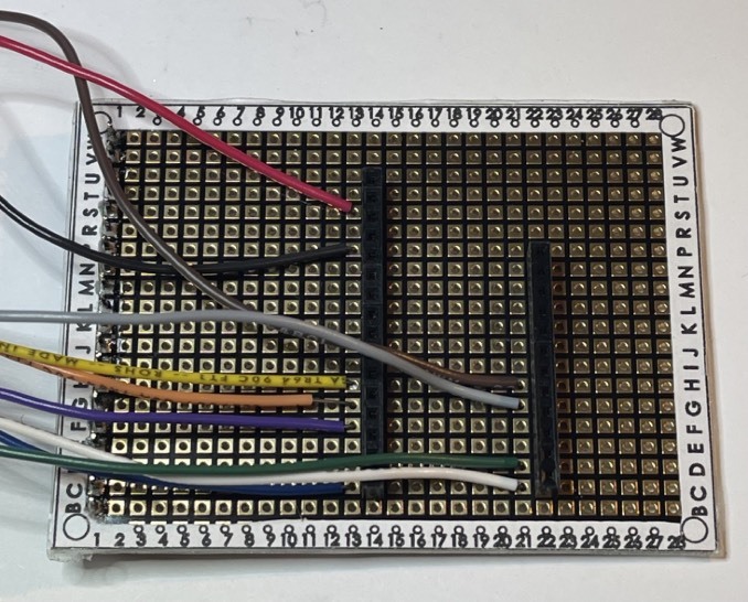
Build Steps - Part 11 Display Board Wiring
Build Steps - Part 12 Display Board Wiring and Headers
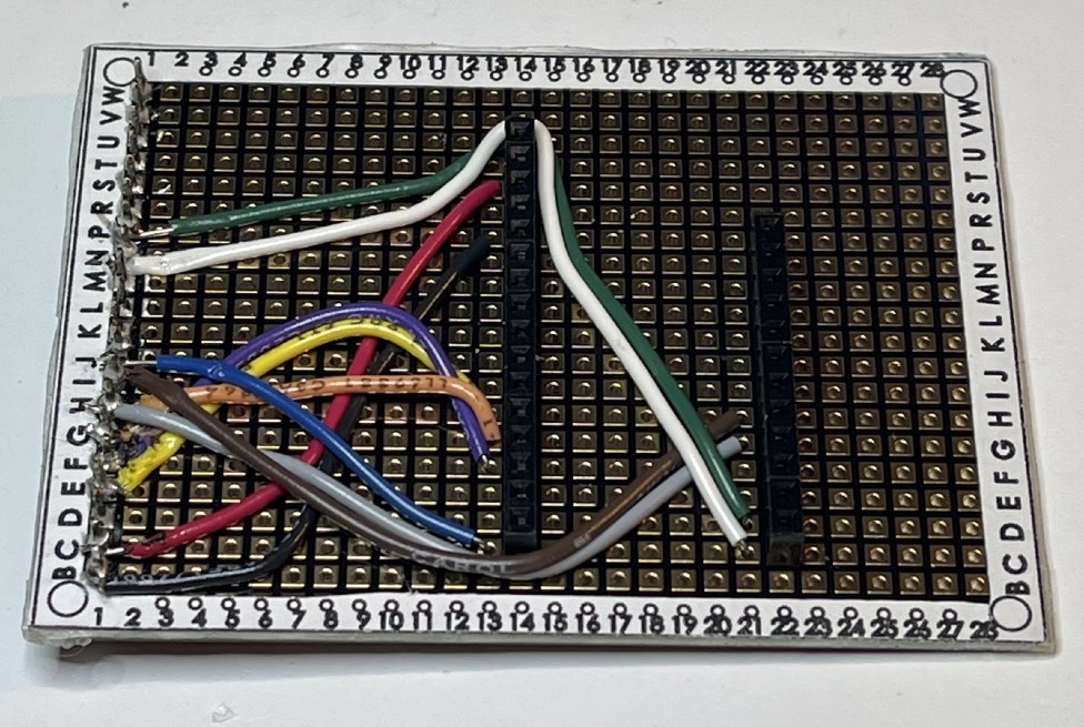
Lines 71 to 80. Connect wires to the header pin positions. Here we show the black wire already soldered and trimmed, and the red wire placed, wrapped around the pin, ready for soldering. Make these connections for each wire to the positions listed in the wiring list.
Build Steps - Part 13 Display Board Wiring and Headers
Line 81. Solder the IM1, IM2, IM3 jumpers closed on the back of the display. Do not close IM0.
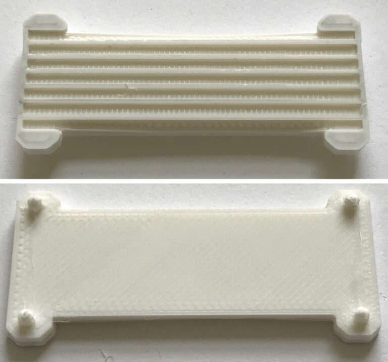
Place the display spacer, 3D printed part “STELLA-1.1 screen spacer in print coords”, on the back of the display.
Apply clear double stick tape to the face of the spacer. Then align the wiring board pins with the holes on the display, to make a sandwich: Wiring board, tape, spacer, display. Trim off the excess tape, and solder the pins to the display board. Trim the excess length of the pins using a diagonal cutter.
Build Steps - Part 14 Mount Display
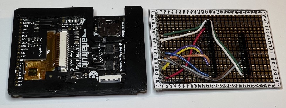
Mount display: align the processor pins on the main board with the socket headers on the display board, on both the 12 and 16 position connections. Press gently to seat the display. Connect the main battery to the power connector.
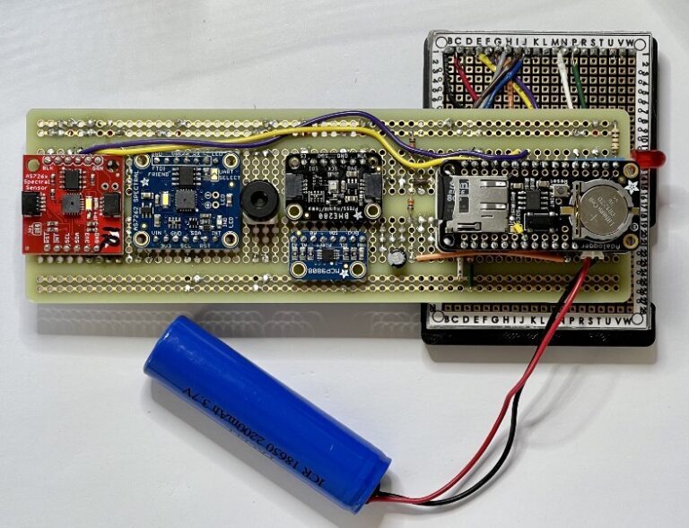
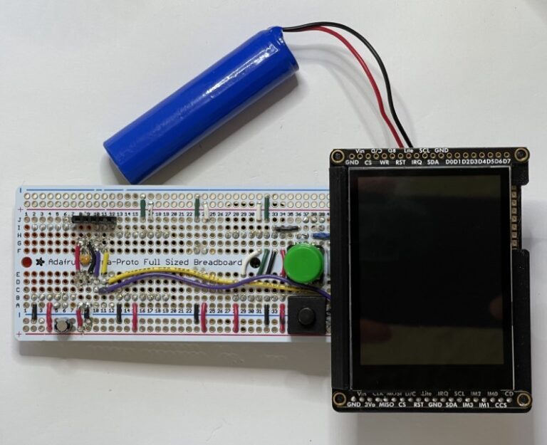
Build Steps - Part 15 STELLA Assembly
Lines 68 and 69. Place short header sockets, 12 pin and 16 pin, on the labeled side of the board. Secure them temporarily with tape and solder them on the other side of the board.
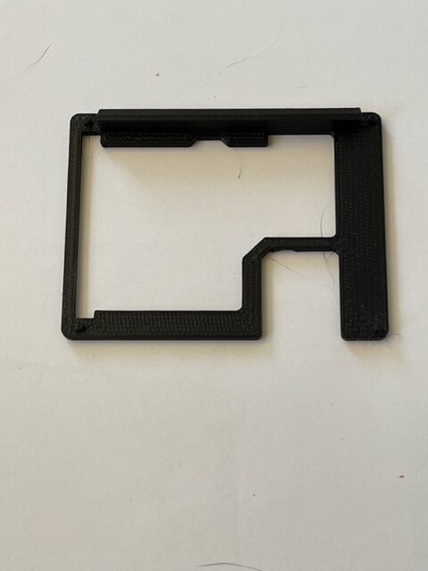
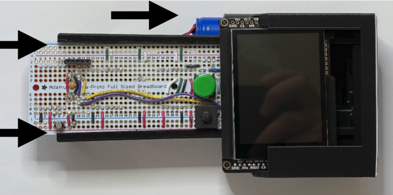
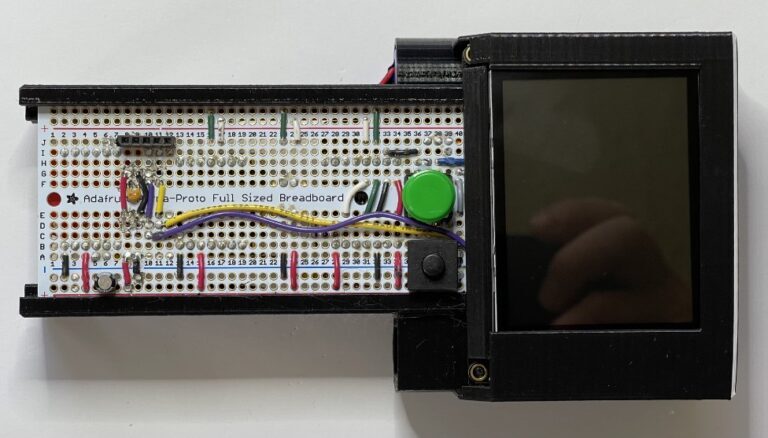
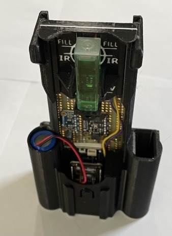
Slide the STELLA assembly into the long grooves of the lower housing, while sliding the main battery into the cylindrical battery holder tube. You may need to press gently on the display to get it to slide into the housing recess. “STELLA-1.1 Lower Housing”
Build Steps - Part 16 STELLA Upper Housing
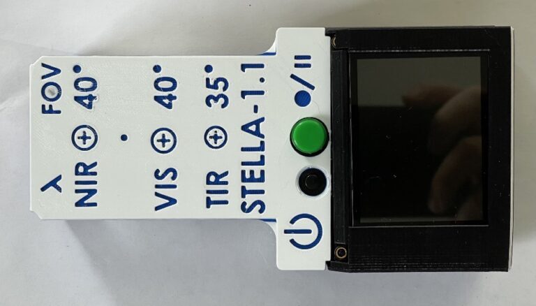
Install Upper Housing: Align the upper housing with the buttons, and press it onto the lower housing so that it snaps into place.”STELLA-1.1 Uppper Housing 3 band”
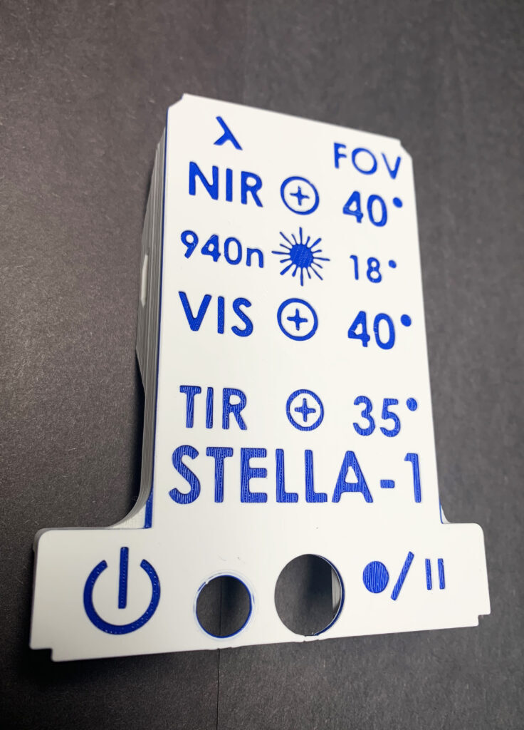
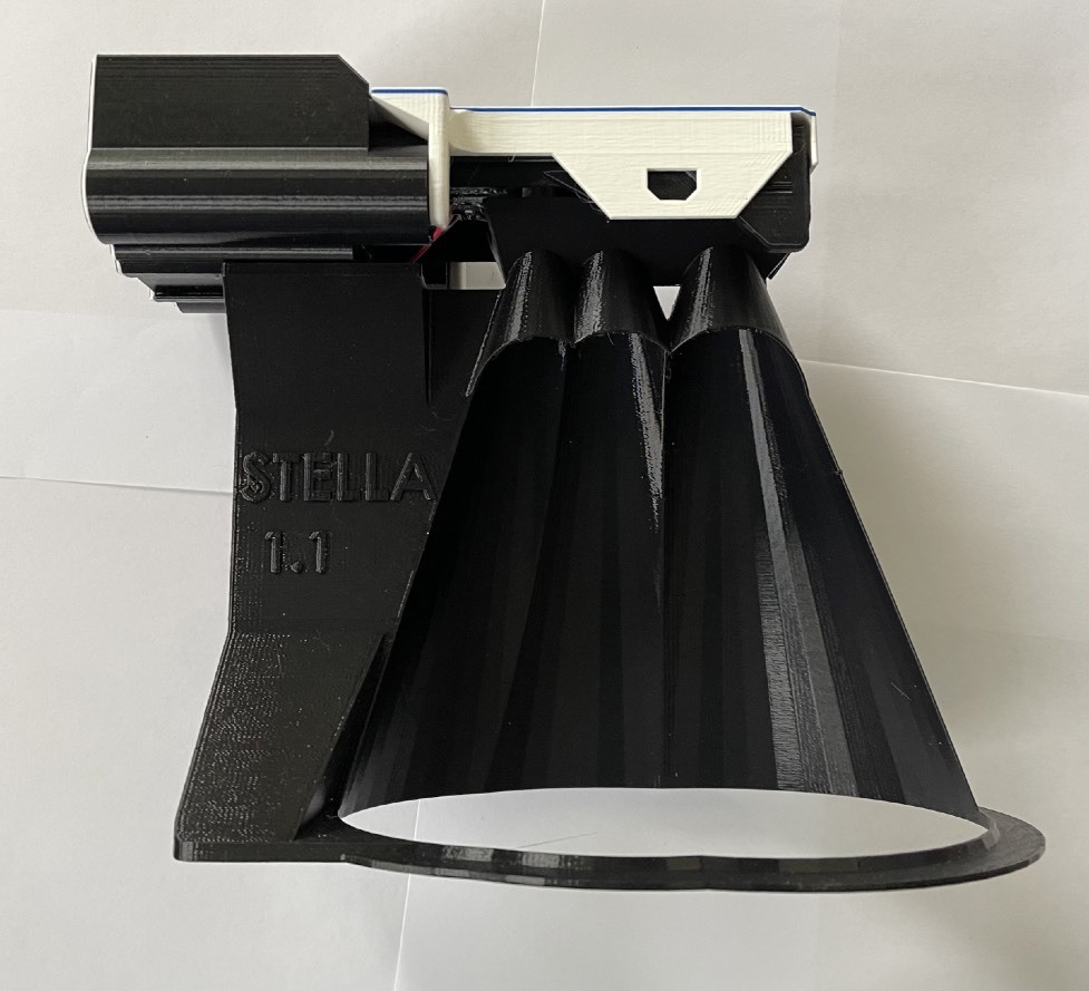
*Build Steps - Part 17 Beam Definition
Install the beam definition model in the dovetail grooves in the lower housing. (You’ll need to remove the LiDAR sensor, if you have it installed.) “STELLA-1.1 beam def in print coords.STL” The model shows the field of view of the spectral sensors and the thermal infrared surface thermometer sensor. You can do the trigonometry to figure out the diameter of the observed area based on how far away the unit is from the surface, given the 40º field of view of the sensors.
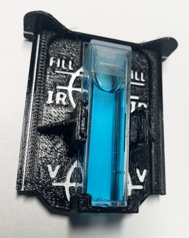
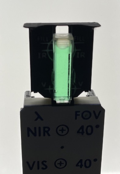
*Build Steps - Part 18 Cuvette Mount
Print the part “STELLA-1.1 cuvette mount in print coords” to hold cuvettes in the field of view of the NIR and VIS sensors. Cuvettes are square test tubes used for testing the optical properties of liquids.
Fill a cuvette with distilled water, and fill another with the liquid you wish to test. Slide the cuvette holder into the dovetail grooves on the lower housing, and snap the cuvette in place to take a measurement. Take two measurements, one of each of the liquids you wish to compare, and subtract the results to get a differential measurement of the transmission spectra of the liquids.
Part 1 — Load CircuitPython onto the Microcontroller.
Locate the CircuitPython file in the STELLA-1.1/CircuitPython_uf2, named “adafruit-circuitpythonadafruit_feather_rp2040-en_US-8.0.5.uf2”. The file is specific to this particular microcontroller. The original source of the file is: https://circuitpython.org/board/ adafruit_feather_rp2040/
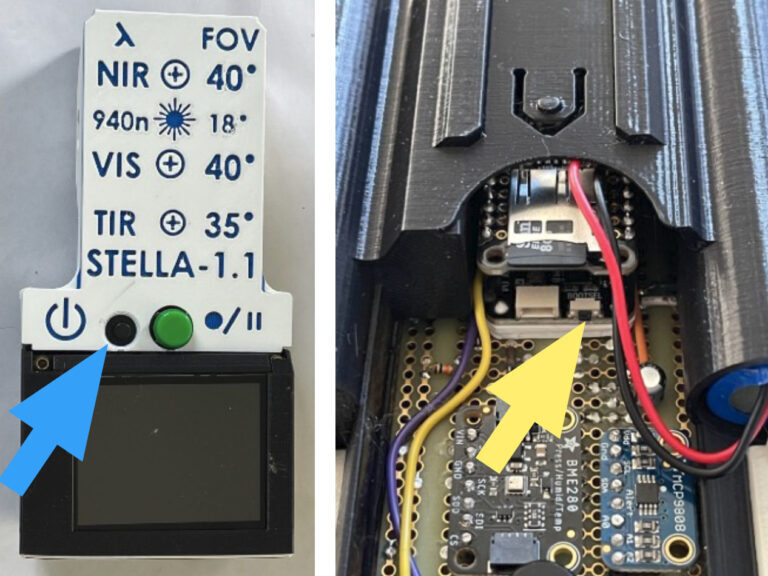
Connect the STELLA to your computer with a USB-C cable.
Press and hold the BOOTSEL button on the end of the microcontroller (yellow arrow). While holding this button, turn on the STELLA with the power button (blue arrow).
The STELLA should show up in your computer’s drive listing as RP1-RP2.
Drag and drop the UF2 file onto the RP1-RP2 drive. The drive will disappear (and the file system will complain about not ejecting the drive properly, that’s normal). The drive will reappear as CIRCUITPY. CircuitPython is now active on the STELLA.
Part 2 — Copy Libraries
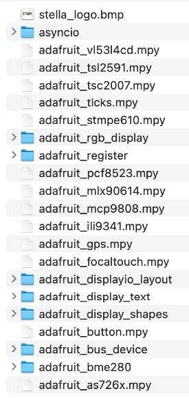
In the STELLA-1.1 files, there is a folder named “code_and_libraries”. Open that folder. Drag and drop the folder labeled “lib” onto the CIRCUITPY drive. The computer will ask if you want to replace the existing file.Yes, we want to replace the existing file.
The lib folder contains the files shown here:
The main STELLA code, and the test codes, use these libraries. The codes will not run without the library files.
Part 3 — Load Mu Editor
To work with the STELLA codes, we need a code editor and serial connection.
Go to https://codewith.mu/ to download the Mu editor, and follow the instructions there for your particular computer.
Click on the Serial button to open the serial dialogue panel, known as the CircuitPython REPL, which stands for Read-Eval-Print Loop.
Click in the REPL panel, and then press ctrl-c to stop the code that is currently running on the STELLA. ( c is for “cancel” )
Press a key to enter the REPL, and you should get a message like this: “Adafruit CircuitPython 8.0.5 on 2023-03-31; Adafruit Feather RP2040 with rp2040”
Press ctrl-d to restart the code. ( d is for “decancel”, but it’s mostly because d is near c )
Boot note: STELLA won’t boot when it is already connected to USB.
To restart/ reboot/ start up, disconnect STELLA from the computer, then power it up (or cycle power off and then on again), and only then reconnect the STELLA to the computer. This limitation seems to be specific to the Feather RP2040.
Part 4 — Run Test Codes
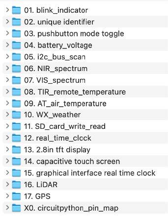
In the “test_codes” folder, there are subfolders that contain codes for testing the devices and systems of the STELLA unit.
Open a subfolder, and copy the “code.py” file within.
Paste it onto the CIRCUITPY drive to run the test code.
The output of the print statements in the code show up in the serial dialogue/ REPL panel.
Press the Load button to display the code in the main Mu editor window.
Make any changes you like to the code, and click Save to save and run the code.
Note that Save is destructive. It will overwrite whatever code is on the STELLA with the code that is currently in the main window.
Run each of the test codes to check that each of the subsystems is functioning properly. If it is not running properly, investigate/ diagnose/ debug, following the debugging instructions

Part 5 — Run the Main Code
From the file folder “code_and_libraries”, copy the code.py file and paste it onto the CIRCUITPY drive. The code will start and run, giving you a functional STELLA instrument.
If the main code does not run properly, investigate/ diagnose/ debug, following the debugging instructions.
Consult the operating instructions for details on how to operate and make measurements with the STELLA.