

STELLA-AQ (Air Quality)
The STELLA-AQ is an essential component of NASA’s Science and Technology Education for Land/Life Assessment instrument family, specifically designed for air quality monitoring applications measuring air temperature, relative humidity, CO2 and particulates.
This user-friendly device features a no-solder assembly process using only connectors, making it particularly accessible for those without technical assembly experience. The STELLA-AQ incorporates specialized sensors to measure various atmospheric parameters, providing valuable data for environmental assessment and citizen science initiatives.
It uses commercial off-the-shelf components, records data to a micro-SD card with time/date stamps, and runs on CircuitPython—a beginner-friendly programming language that requires no coding expertise to operate. The instrument enables users to collect meaningful air quality data while learning about remote sensing technology, environmental science, and data analysis.
To build your own STELLA-AQ download the STELLA-AQ files and follow the build steps.
STELLA-AQ Highlights

“The Golden Pathos Theory” – Single Plant Testing
Students test common houseplants as space life-support systems using STELLA-Q2 sensors to measure CO2 consumption. …
Lynn Nichols now PK-12 Director of Education Technology at Gilman, showcases how NASA's STELLA technology …
Bringing NASA Technology to the Classroom: One Educator’s Mission to Transform STEM Learning
Lynn Nichols transforms STEM education using NASA's STELLA instrument, bridging 3D printing, robotics & space …
Build Your Own STELLA-AQ
| Index | Quantity | Description | Unit Price | Vendor Used | Manufacturer PN |
|---|---|---|---|---|---|
| 1 | 1 | SPARKFUN THING PLUS - RP2040 | 19.86 | Sparkfun | DEV-17745 |
| 2** Alternative Screen | 1 | Monochrome 0.96" 128x64 OLED Graphic Display | 17.50 | Adafruit | 326 |
| 2** Primary Screen | 1 | ADAFRUIT GRAYSCALE 1.5 128X128 OLED | 22.50 | Adafruit | 4741 |
| 3 | 1 | STEMMA QT PCF8523 RTC | 4.95 | Adafruit | 5189 |
| 4 | 1 | SENSOR HUM/PRESS I2C/SPI BME280 | 14.95 | Adafruit | 2652 |
| 5 | 1 | STEMMA QT SCD-40 CO2 HUMID TEMP | 44.95 | Adafruit | 5187 |
| 6 | 1 | STEMMA QT PMSA003I AIR QUALITY | 44.95 | Adafruit | 4632 |
| 7 | 5 | JST SH 4-PIN CABLE - QWIIC COMPA | 0.95 | Adafruit | 4210 |
| 8 | 1 | BATTERY LITHIUM 3.7V 2.2AH | 9.95 | Adafruit | 1781 |
| 9 | 1 | BATTERY LITHIUM 3V COIN 12.5MM | 0.82 | Adafruit | 380 |
| 10 | 1 | JST-PH2 EXT CBL 2PIN SWITCH 20 | 2.95 | Adafruit | 3064 |
| 11 | 1 | 64MB MICRO SD MEMORY CARD | 3.50 | Adafruit | 5249 |
| 12 | 1 | CABLE C PLUG TO C PLUG 3.28' | 9.95 | Adafruit | 4199 |
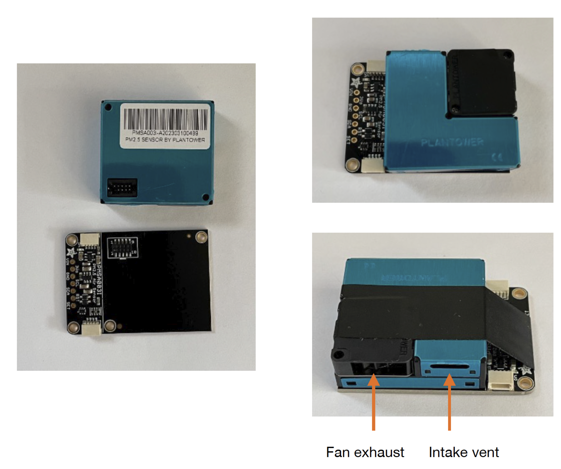
Secure the particulate sensor to its circuit board:
The particulate sensor is only connected the the circuit board by a single connector.
To keep the sensor from falling off after the instrument is assembled, place the sensor on
the board, and then secure it with one wrap of electrical tape, along the midline of the sensor, between the two off board
connectors. Keep the fan exhaust and intake vent clear, so the sensor will function.
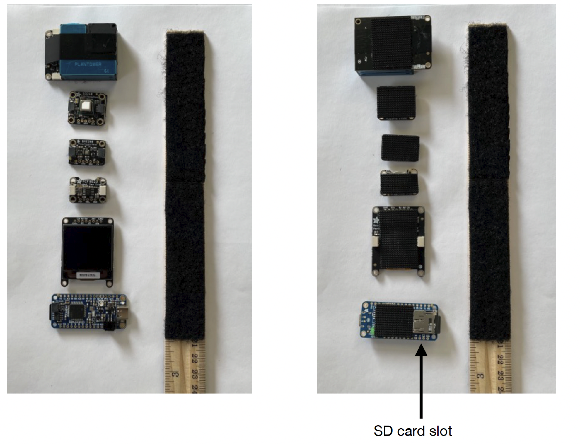
Lay out the components in the order that they will go onto the ruler base.
Cover the ruler base, from 4 to 12 inches, with sticky back loop face fastener, in a strip or in multiple squares.
Flip the components over, and add hook face sticky back fastener to the middle rear of
each component. Keep the fastener clear of the SD card slot, so the adhesive doesn’t
interfere with inserting or ejecting the micro SD card.
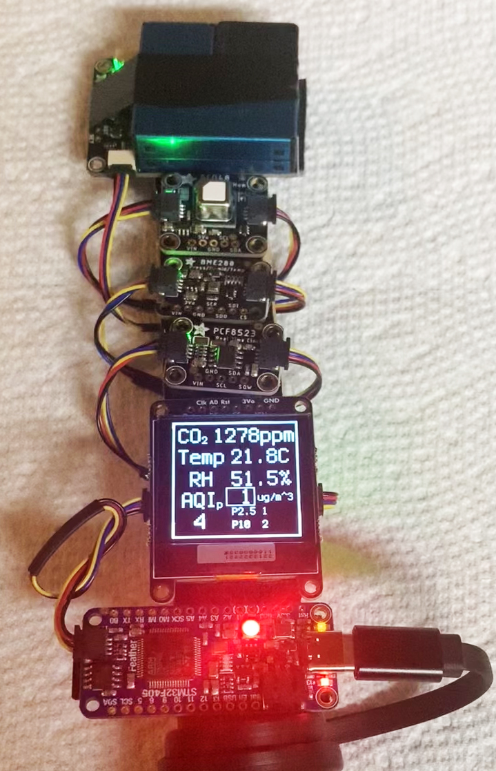
Connect the cables.
The connectors are mechanically polarized, so you can’t plug them in the wrong way around. The side of the connector that shows
a four bits of exposed metal should be oriented towards the circuit board on the component.
Connect the cables as shown, connecting all the components in a “daisy-chain” fashion. You can tuck the wires into the space
between components to neaten the wiring.
Add 3 to 4 inches of loop face fastener to the back of the ruler. Add pieces of hook face fastener to the battery and the back of the
power switch.
Attach the switch and battery, and wrap the power cables around the ruler before making the connections between the battery and
switch, and between the switch and the microcontroller. Secure the battery with a single wrap of electrical tape. Once you
have assembled your STELLA-AQ, follow the programming instructions to get it working!
Step 1: Programming STELLA-AQ microcontroller
These instructions will guide you to load the CircuitPython onto the SparkFun Thing Plus RP2040 and will work equally well for PC
computers running Windows and Macintosh computers running OSX.
Open a web browser on your computer, and navigate to https://circuitpython.org/
Click on the Downloads button.
In the search panel, enter Thing, and then select the Thing Plus RP2040.
(https://circuitpython.org/board/sparkfun_thing_plus_rp2040/)
Click the purple Download the UF2 now button to download the CircuitPython boot Mle. Look
in your downloads folder to locate the Mle, which will be named adafruit-circuitpython-sparkfun_thing_plus_rp2040-en_US-x.x.x.uf2
Where the x‘s will show as the version number.
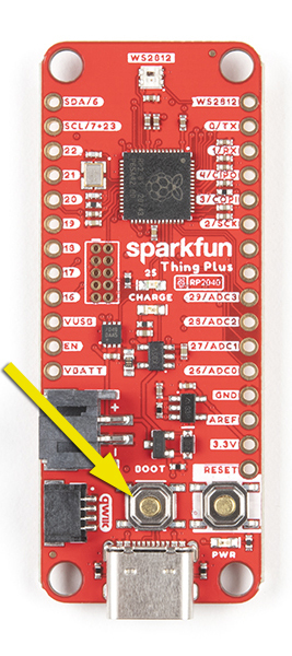
Locate the BOOT button on the Thing Plus. Hold the button down while at the same time connecting the Thing Plus to your computer’s USB port. Then let go of the button.
You will see an external drive appear in your computers listing of locations. The drive will be called RP1-RP2.
Copy the UF2 Mle you downloaded onto the RP1-RP2 drive. It takes a few seconds to perform this copy.
The RP1-RP2 drive will disappear, to be replaced by a drive called CIRCUITPY. If
your computer asks, allow this drive to connect. If your computer offers to set up a USB keyboard, cancel that option.
You have now installed the CircuitPython system on your Thing Plus RP2040.
Step 2: Setting the Time
1. Open Mu Editor.
2. Turn on the STELLA, and plug it in to your computer.
3. Click on the Serial button at the top of the Mu window.
4. In the Serial Dialogue panel that opens at the bottom of the Mu window, you should see a line of text that loads every second:
“Memory B: Used xxxxxx /Free xxxxxx recording…”
That tells you that Mu is communicating properly with the STELLA.
5. Open the Finder (on a Mac) (File Explorer in Windows). Find the CIRCUITPY drive in the Mle list. Click on it to load it into the
window. You should see three items: boot_out.txt, code.py, and a folder called lib.
6. In another Finder/Explorer window your computer, in the code files that you downloaded for programming the STELLA, open the folder called test_codes. In there you should find a folder called real_time_clock, and in that folder you should Mnd a Mle named code.py
7. Copy that code.py file, and paste it onto the CIRCUITPY drive. (Drag and drop should also work) The system will ask you if you want to replace the existing code.py file, and you should choose to Replace.
8. Now go back to the Mu window. In the Serial panel it should be printing out the date and time, once a second. That shows that you have the real time clock test code running on the STELLA. The STELLA screen itself should be either blank, or showing the same printout as you are seeing in the Serial dialogue.
9. Now click on the Load button at the top of the Mu editor. You should see the contents of the CIRCUITPY drive. If you see some other contents, change the choices so that you are looking at the CIRCUITPY drive. (If you save a Mle somewhere else on the computer, it will not run on the STELLA, but Mu doesn’t warn you about that, or offer a Save As button to correct that)
10. In the Load window, select the code.py Mle on the CIRCUITPY drive, and the real time clock test code should load in the Mu window.
11. There is a line of code that reads “if False”. Change that line to “if True”. It’s important to get the capitalization correct (lower
case if, upper case T in True).
12. Open a web browser window, and navigate to time.is/UTC to get a readout of the current global universal time.
13. A few lines below the “if True” line is a line “t = time.struct_time((…))” That line is a bit out of date by now. Change the line as
follows: I’m setting my STELLA as I am writing this, so the line now should read:
t = time.struct_time(( 2022, 09, 30, 19, 38, 00, 5, -1, -1))
I’ve set the seconds to 00. 5 designates the day as Friday, and the -1, -1 tells the clock not to set the day of the year or ‘is daylight
savings’ Melds.
14. Wait for the web UTC clock to get within two seconds of the time you’ve put in the time.struct line, and then click the Save button at the top of the Mu editor. That sets the real time clock module on the STELLA. The printout in the Serial panel should show
the correct time now.
15. To make sure we don’t save again and reset the time incorrectly, change the “if True” line to “if False”. Then save the code again. The Serial printout should continue to show the correct time.
16. Now go back to the Finder/ Explorer, and locate the STELLA-AQ-code-and-libraries folder. . Copy the code.py from there to the CIRCUITPY drive, choose to Replace the existing file, and the STELLA should run the full instrumentation, now with the correct time.
Step 3: Programming STELLA-AQ
Now that you have CircuitPython installed on the microcontroller, you are ready to program your STELLA-AQ.
1. Download the .ZIP file that contains the latest software.
2. In the folder labelled “code and libraries”, copy the folder named “lib”, and paste it onto the CIRCUITPY drive. (You can also drag and drop it to the CIRCUITPY drive.) You may get a message that the folder already exists; choose to replace the existing folder.
3. From the same “code and libraries” folder, select the file named “code.py” and copy/paste or drag/drop it onto the CIRCUITPY
drive. The code should start up (it takes 12 seconds to boot) and you will have a working STELLA spectrometer. We’ve written the
code so that it is tolerant of missing devices, so even if you haven’t got all the parts it should still work.
4. In the “test codes” folder, there is a subfolder called “real time clock”. Inside that folder is a Mle named “code.py” Copy and paste that file to the CIRCUITPY drive to set the real time clock. Follow the detailed instructions here to set the clock.
5. Once the clock is set, repeat Step 3 to install the STELLA instrument software.